For the Capstone Design project at Hanyang University, my partner and I built a remote-controlled mobile robot with the aid of my research advisor, Prof. Joonhong Lim.
 |
| The System Overview |
As shown above, the overall system mainly consists of three parts: robot, main-controller, and sub-controller.
 |
| Mobile Robot |
The robot is equipped with two microcontrollers (ATmega128) (4) as a master-slave pair, four DC motors (IG-32M) driven by four motor drivers (LMT18200T) (3), one C328 camera module mounted on two servo motors (5), three ultrasonic sensors (SRF04) (6), and two bluetooth modules (ESD-1000 and ACODE-600) (2). Two Li-Poly batteries (7.4V and 12V) (1) are used to power up all parts: 7.4V is regulated to 3.3V for the camera, bluetooth modules, and ultrasonic sensors and to 5V for the AVR MCUs and servo motors.
I designed all circuit schematics using the OrCad Capture program and did all the soldering jobs all by myself.
 |
| Schematic of the Main-Controller (Master) |
 |
| Backside of the mobile robot PCB |
I also programmed all the necessary codes for the robot and the sub-controller using a CodeVisionAVR integrated development environment. Four motors are controlled by two PWM signal lines, each of which is connected to the left- or right-side wheels so that both side wheels can run in opposite sides (forward and backward) at the same time. Thus the robot is able to turn its direction without even going forward or backward, and in addition it can make curves by differentiating the speeds of the both side wheels. I also did Hardware-in-the-Loop (HIL) simulations to test the PI controller codes to control the motors more accurately.
Using MFC libraries in a Microsoft Visual C++ 6.0 environment, I programmed a main-controller as a graphical user interface (GUI) to control the robot wirelessly. The main program has a communication function which connects to the bluetooth module by RS232 and then transmits its control commands to the robot wirelessly via the bluetooth module. The main-controller program can control the speed and direction of the robot as well as the position of the camera. It also displays the raw image data from the camera as a JPEG format and has some basic image processing functions (sharpening, blurring, gamma, and edge-detection).
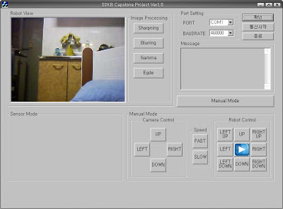 |
| Main-Controller Program |
I also made a sub-controller by customizing a PS2 controller, which is controlled by the ATmega128L microcontroller. I analyzed all the internal protocols of the PS2 controller and hooked up the control signal lines to the microcontroller's digital input/output ports. This sub-controller also communicates with the robot via a bluetooth module and sends control various commands (go up/down, turn left/right, speed up/down, etc.). The possible command combinations from multiple buttons were very rich, so the PS2 controller was a perfect choice for the sub-controller.
 |
| Customized PS2 Sub-Controller |
 |
| Customized PS2 Sub-Controller |
The sub-controller also displays an image received from the camera on a CSTN 1.5' color LCD, but due to the low performance and limited memory of the MCU the frames per second was quite low. So I decided to send all the image data to the main-controller.


No comments :
Post a Comment